Senior Design Project
Mechanical Design
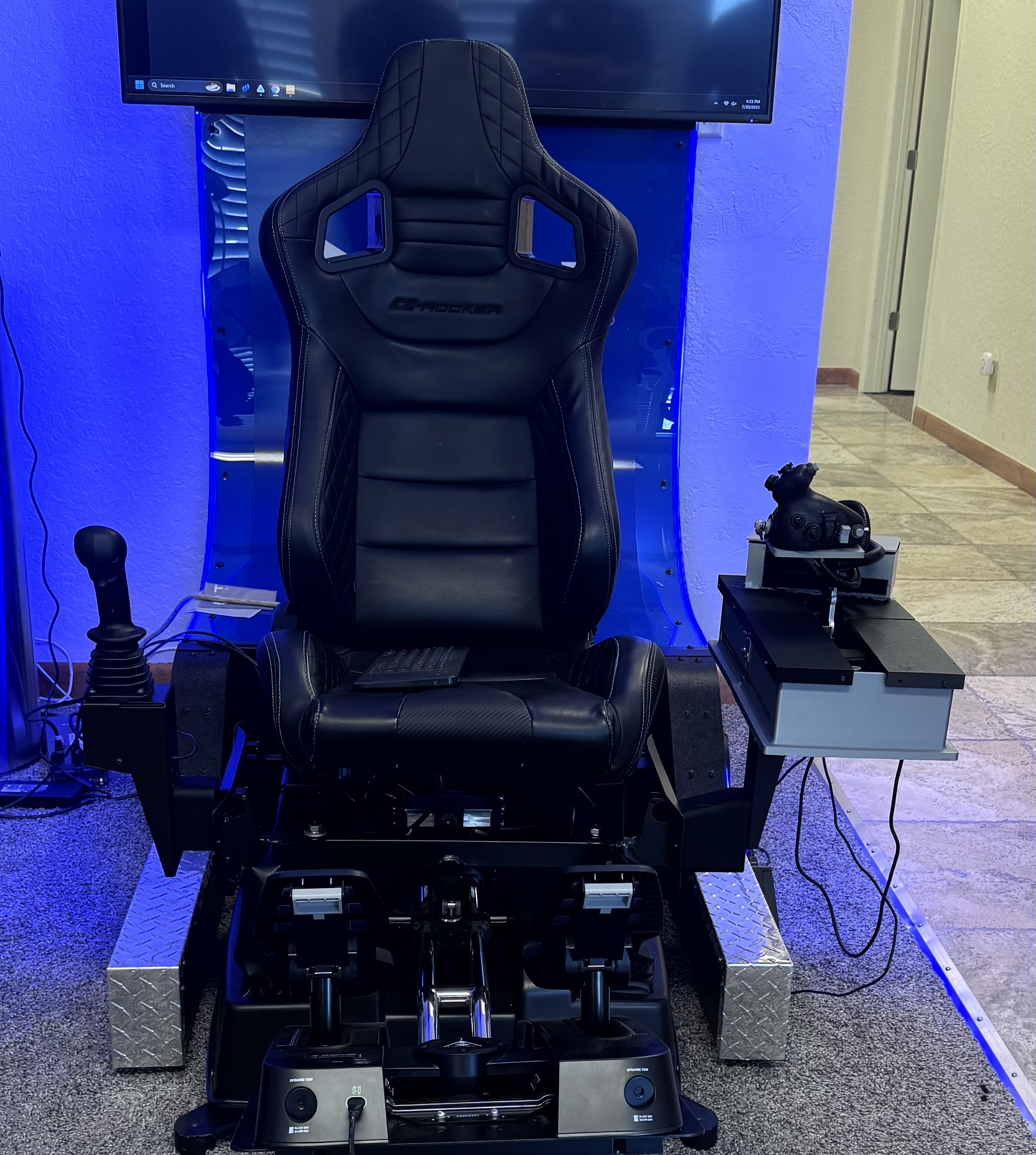
The F-35 Throttle Controller was engineered to replicate the ergonomics, detents, and resistance characteristics of the actual aircraft throttle while remaining affordable and modular. The throttle had to mount securely to Talon Simulations’ 2-DoF motion platform and align with in-game cockpit geometry for a seamless VR experience. Benchmarking against commercial products from Wraith Systems, RealSimulator, and Bugeye revealed a gap: existing throttles were either prohibitively expensive or lacked authentic feel. Our design sought to bridge this gap by combining realistic tactile response with manufacturability under a $1,000 budget.
From a requirements standpoint, the throttle needed to reproduce idle, military power, and afterburner detents with both tactile and mechanical fidelity. Target resistance was set between 1–3 pounds for normal use, with peaks up to 5 pounds under high-performance flight conditions. To meet these targets, the design incorporated a magnet-based detent system and a DryLin linear rail mechanism that provided smooth travel with distinct stops at critical throttle positions. Materials included reinforced thermoplastics via 3D printing for housings, and machined aluminum for high-stress components.
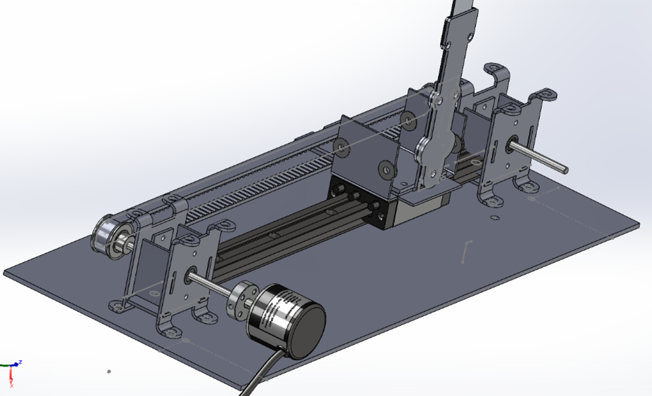
A belt and pulley system was modeled within the CAD environment to simulate the throttle’s motion transfer mechanism. This subsystem converts the physical motion of the throttle lever into a trackable signal that can be interpreted by the flight simulator software. Linear motion analyses were performed to evaluate tension, deflection, and backlash within the belt system, ensuring consistent performance and accurate positional feedback across the entire throttle range. The CAD model served not only as a visualization tool but also as a functional design validation platform, allowing the team to troubleshoot mechanical interactions before prototyping began.
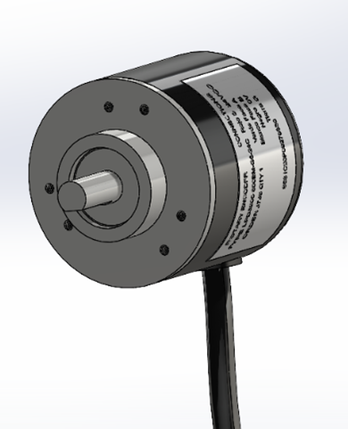
To further enhance fidelity, the team modeled the Taiss optical rotary encoder that provides high-resolution throttle position feedback. The model reflected shaft diameter, mounting points, and electrical interfaces to ensure proper integration. Including the encoder in the assembly allowed for verification of spatial compatibility and the design of custom mounts and couplings. This enabled precise alignment with the throttle’s moving components and streamlined system integration planning.
The Igus DryLin® T HKA carriage played a critical role in providing precise linear motion control and customizable resistance during operation. The carriage’s adjustable side knob allowed fine-tuning of bearing preload against the rail, introducing variable frictional resistance along the axis. This feature simulated different throttle tension profiles, such as the increased resistance when pushing into afterburner zones, without requiring additional springs or dampers. Rear-positioned Allen screws locked the carriage structurally, eliminating undesired lateral or vertical play. This constrained the system to pure x-axis motion, preventing wobble or tilt and ensuring clean, repeatable travel for consistent sensor readings.
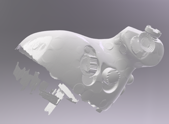
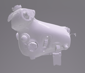
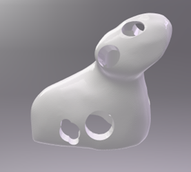
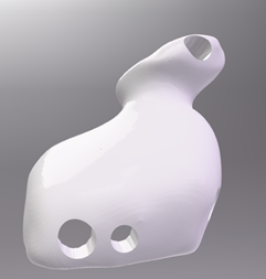
To accurately reproduce the F-35 throttle grip, known as the cowpie, the team conducted a 3D scan at the Air Force Agency for Modeling and Simulation (AFAMS). Using a CrealityScan 3D scanner, we captured the geometry of a reference throttle directly from an operational simulator. This scan provided the baseline dimensions and contours of the grip, which are not publicly available.
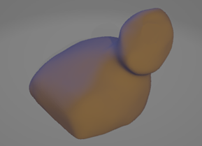
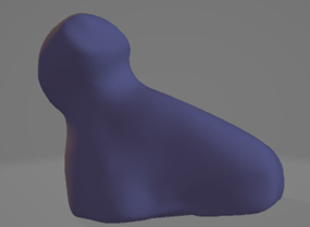
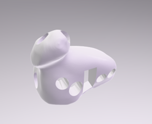
The raw scan data presented challenges: many surfaces were patchy or uneven, and holes existed where buttons and switches had been scanned. To address this, the mesh was imported into Blender Studio where the geometry was smoothed, gaps were filled, and button holes were reconstructed. The repaired mesh was then transferred into SolidWorks, where precise cutouts were modeled for each switch, hat, and rotary input. This hybrid workflow of scanning, mesh editing, and CAD refinement allowed the team to create a dimensionally accurate and manufacturable throttle grip.
Once refined, the model was 3D printed using PLA for rapid prototyping. This allowed the team to iteratively test button placement, ergonomics, and internal clearances. The iterative prototyping process ensured that by the time the actual switches arrived, the grip geometry was already optimized for both fit and function. By leveraging 3D scanning and digital mesh refinement, the team shortened the development cycle while maintaining fidelity to the F-35’s true control geometry.
Overall, the mechanical design provided both a digital validation tool and a manufacturing roadmap. By combining linear rails, belt-driven motion transfer, rotary encoders, and ergonomically modeled grips, the design laid a robust foundation for physical prototyping. This approach ensured that once built, the throttle would deliver smooth travel across its 9-inch range, crisp magnetic detents, and reliable positional accuracy.
Electronics Integration
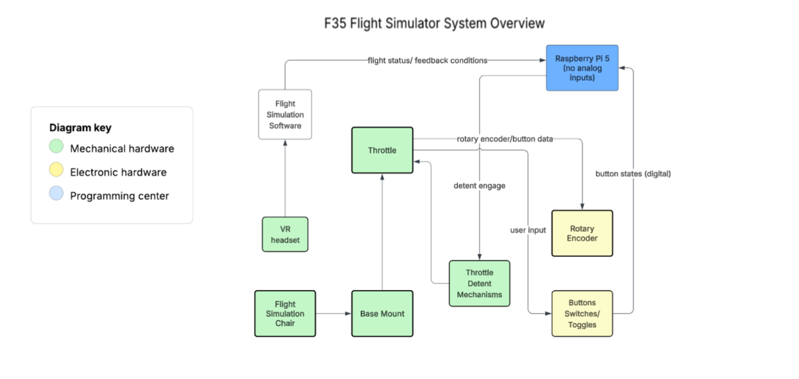
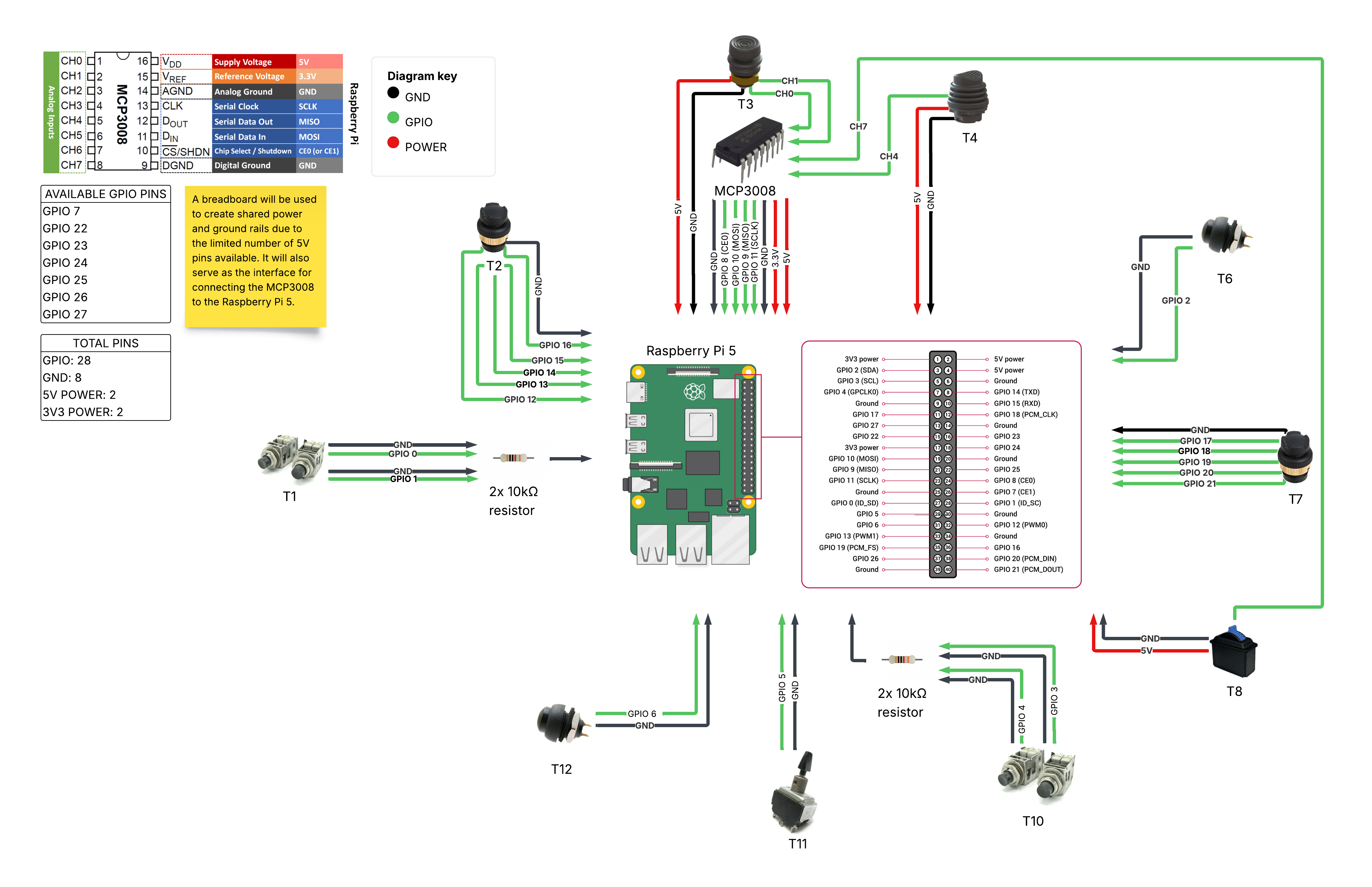
The throttle’s electronics were built around a Raspberry Pi 5 acting as the central controller. Because the Pi has no native analog inputs, we added an MCP3008 10-bit ADC on SPI to read analog devices (e.g., multi-axis hats and potentiometers), while the Pi’s GPIO handled the digital switches, toggles, and the Taiss optical rotary encoder used for primary throttle position. In total, the system supported ~29 inputs across the grip and base.
The wiring harness routed inputs to a small breakout/terminal board and then to the Pi. Digital lines used pull-ups/pull-downs and software debouncing to tame switch chatter, while analog lines fed the MCP3008’s CH0–CH7 channels via short runs and protective voltage dividers where necessary to keep everything within 3.3 V logic limits. The encoder produced clean quadrature pulses read by the Pi with edge interrupts. A simple health-check layer in software flagged lines that were floating or saturated, speeding up troubleshooting during bring-up.
On the software side, a Python service on the Pi sampled the MCP3008, polled/latched GPIO states, applied debounce and dead-zone filters, and packed everything into a compact message sent over UDP to a PC client. There, inputs were mapped to the simulator using vJoy and SimConnect so the throttle appeared as a native controller in Microsoft Flight Simulator and DCS World.
The build also came with real-world hurdles. Some critical components arrived late, so we repurposed buttons from older controllers that lacked documentation. That forced careful bench testing to determine pinouts, signal types, and required conditioning. Wiring took longer than planned because we worked methodically to avoid shorts and over-voltage conditions—measuring each rail with a multimeter, confirming grounds, and validating that any 5 V devices were safely level-shifted or isolated from the Pi’s 3.3 V logic.
A major issue came from the Taiss optical rotary encoder. Although rated for 5–24 V operation, we discovered during testing that its internal regulator required at least ~7 V to output stable and accurate signals. At 5 V, the readings were noisy and inconsistent. The solution was to power the encoder from a dedicated higher-voltage supply instead of the Pi’s 5 V rail, while keeping the signal lines properly level-shifted for compatibility. This ensured accurate position tracking without risking the Pi’s GPIO.
Despite the administrative delays and scavenged parts, the final integration was stable and repeatable, with clean encoder counts and reliable button states across the full throttle range. The architecture delivered a responsive, low-latency pipeline from physical inputs to simulator actions, while remaining maintainable: analog expansion is as simple as assigning another MCP3008 channel, and additional digital inputs can be added through spare GPIO and I²C/SPI expanders if needed.
Software Development
The software architecture for the throttle system was designed to bridge low-level hardware inputs with high-level simulator commands. On the Raspberry Pi 5, a Python service continuously polled GPIO states, read analog channels from the MCP3008 over SPI, and counted quadrature pulses from the Taiss rotary encoder. Custom debounce and cooldown logic filtered mechanical switch noise, while analog dead-zones stabilized the output of multi-axis hats and joysticks. This ensured that user inputs were responsive without being jittery or over-sensitive.
Processed inputs were encoded into a lightweight packet and transmitted to the PC via UDP sockets. This networking layer kept latency extremely low while allowing the Pi to operate headless. On the PC side, the throttle inputs were mapped through vJoy to appear as a virtual joystick, enabling direct compatibility with Microsoft Flight Simulator and DCS World. For MSFS, additional integration was achieved through SimConnect, which allowed custom events and throttle positions to be read natively by the simulator.
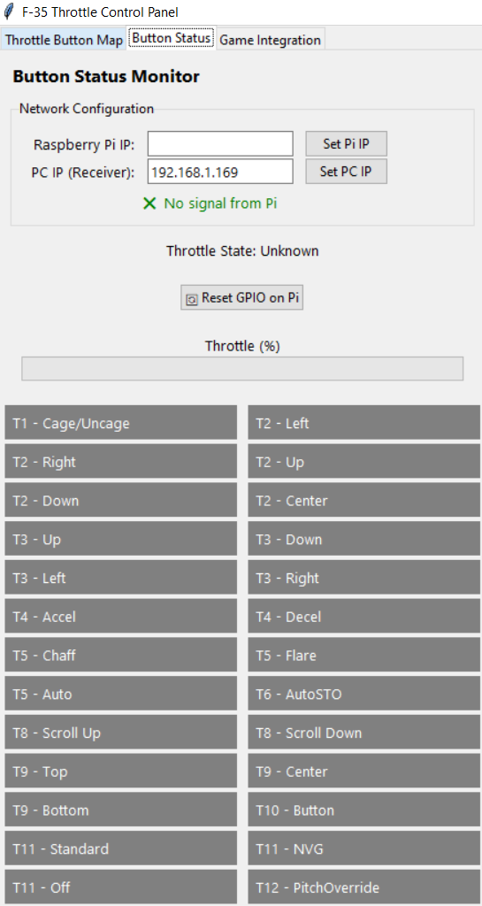
To simplify setup and testing, the team built a Python/Tkinter-based GUI that acted as the user’s front end. The GUI connected directly to the Pi without requiring repeated manual configuration—only the Pi’s IP address needed to be entered once for each new Wi-Fi network. After that, the GUI handled connections automatically, launching the Pi-side program to stream inputs to vJoy. The GUI supported live tracking of all throttle inputs, including button presses, toggle states, and throttle position. This allowed users to visually confirm that hardware signals were being correctly captured before entering the simulator. The GUI also featured a dedicated instructions tab with setup guidance, making the system approachable for new operators and providing troubleshooting steps for connectivity or mapping issues.
Several issues arose during development. Analog hats initially proved too sensitive, producing rapid toggling from small finger movements. This was corrected with expanded dead-zones and short cooldown timers. The rotary encoder introduced lag when polled directly via interrupts, which was solved by switching to a threaded listener using the pigpio library. Button mapping for 29 inputs also required careful organization, especially to align with official F-35 HOTAS documentation so that simulator functions matched real-world control locations.
Through these refinements, the software achieved real-time responsiveness and robust input handling. Together with the electronics and mechanical systems, it completed the end-to-end throttle controller pipeline: from user action on the grip, to microsecond-level signal processing, to full integration within modern flight simulation platforms.
Testing & Validation
After completing the integration of mechanical, electrical, and software systems, the team conducted a comprehensive testing and validation campaign to ensure the throttle performed reliably under real-world conditions. The process began with bench testing of wiring and GPIO channels. Using a multimeter, each connection was verified for continuity and correct voltage levels to prevent shorts or over-voltage damage to the Raspberry Pi. Special care was taken with repurposed switches, which lacked documentation and required empirical testing to identify pinouts.
Validation of the rotary encoder was a critical step. Early tests revealed unstable counts when powered from 5 V, which was traced to an internal regulator that required ~7 V minimum for proper operation. Once the encoder was powered from an external supply and signals were level-shifted for compatibility, it delivered consistent, high-resolution tracking across the full 9-inch throttle throw.
On the mechanical side, the Igus rail carriage and linear motion system were tested for smoothness, alignment, and long-term wear. The carriage maintained precise x-axis motion without lateral play, ensuring reliable input readings. Detent mechanisms were exercised repeatedly to confirm crisp engagement at afterburner and idle zones, simulating the tactile feedback of a real throttle.
The GUI validation phase confirmed that all 29 inputs could be live-tracked in real time without lag or false triggering. The interface also successfully launched the Pi-side program and maintained stable UDP communication, with the “No signal from Pi” status working as a diagnostic tool during simulated disconnects.
Finally, the system underwent simulator integration testing. Inputs streamed from the Pi were mapped through vJoy and SimConnect into Microsoft Flight Simulator and DCS World. Throttle movement, button presses, and toggle states were accurately reflected in the cockpit environment, validating the end-to-end control pipeline from hardware grip to virtual aircraft.
While force feedback was not implemented in this version of the throttle, the mechanical detents and friction adjustments provided sufficient tactile realism for immersive flight simulation. The testing campaign verified that the throttle was both robust and responsive, laying the foundation for future iterations that could introduce haptic or force-feedback elements.
Future Improvements
While the throttle system successfully met its functional requirements, several areas for improvement were identified during development and testing. One of the most immediate challenges was part sourcing. Delays in component deliveries forced the team to repurpose buttons from older controllers, which created documentation gaps and extended wiring time. Future iterations would benefit from ready access to hardware, reducing project risk and build time.
Another limitation was housing size. The throttle body was constrained by the available 3D printers, leading to a modular print-and-assemble process. With access to a larger printer, or a housing redesign optimized for available tools, the system could achieve a stronger and more seamless structure. Similarly, in-house 3D printing of buttons would reduce production expenses while giving the team full control over ergonomics and durability.
Mechanically, improvements to the linear rail system could further enhance stability. A dual-rail configuration would reduce wobble and distribute forces evenly along the lever, improving long-term wear and input consistency. Additionally, the detent system could be made more customizable by replacing static magnetic detents with a cam/roller spring system, allowing pilots to adjust detent resistance profiles to match different flight scenarios.
On the electrical side, the team identified an issue with wiring noise. During demonstrations, overlapping button wires caused phantom activations, where random button presses registered without user input. This will be addressed in future revisions by improving cable management, adding shielding where necessary, and spacing parallel wire runs to reduce interference. Together, these refinements would significantly improve system reliability and polish for long-term use.